
Lab1 Booting a PC
Lab1: Booting a PC
Part1 PC Bootstrap
Getting Started with x86 assembly
整个实验使用的汇编语言都是x86,因此需要了解x86的语法和一些技巧。需要注意的是使用语法格式是AT&T风格而不是Intel风格,具体来说,一个显著的区别在于:
1 | mov src, dst # This is AT&T style |
Simulating the x86
实现环境不采用实机而是通过QEMU模拟器,更为方便。QEMU可以提供远程调试模板,这个在之后的跟踪内核启动指令有用。
通过make生成内核映像(obj/kern/kernel.img),它包含两部分:boot loader(obj/boot/boot)和kernel(obj/kernel),然后通过QEMU加载该映像启动内核。
实现提供了一个Makefile文件,里面有准备好的命令,敲入make qemu就能启动PC了: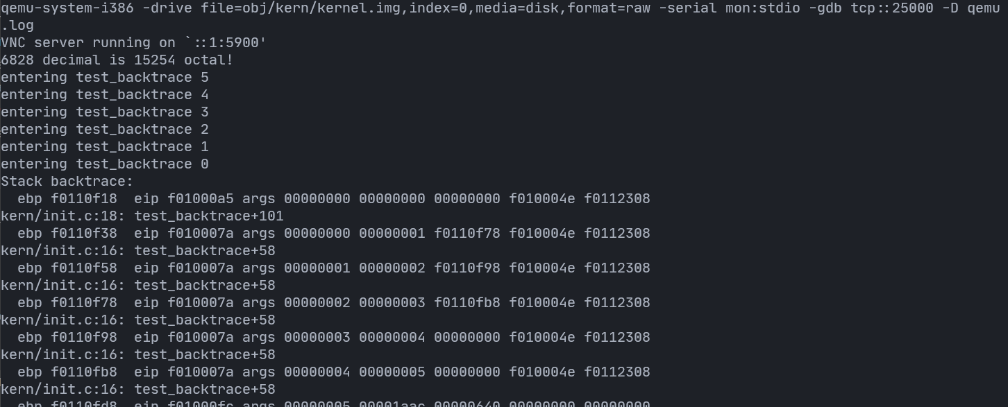
退出方式:Ctrl+a x
现在内核提供了一个显示器(Monitor),可以接受键盘输入,开始可以输入的有效命令只有两个: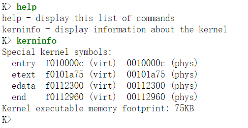
调试该内核,则使用如下指令1
2
3
4
5// terminal window 1
make qemu-gdb
// terminal window 2
make gdb
The PC’s Physical Address Space
1 | +------------------+ <- 0xFFFFFFFF (4GB) |
The ROM BIOS
使用gdb调试内核。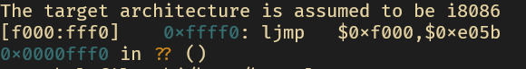
开始执行指令的物理地址为0x000ffff0,对照内存空间不难发现这是在64KB BIOS的顶部
第一个指令是ljmp,跳转到的地址为cs: 0xf000, ip: 0xe05d,即0xfe05d,至于为什么要跳转,文档给出的理由是只有16字节啥都干不了,所以要跳到BIOS的前面去(0xf0000~0xfffff)。
BIOS安置中断描述符表(interrupt descriptor table)和初始化各种设备(比如VGA display)。
在初始化PCI总线和所有BIOS知晓的重要设备后,它搜索可启动(bootable)设备,比如软盘(floppy),硬件驱动(hard drive),CD-ROM。最终,找到了可启动硬盘,BIOS从中读取boot loader,并将控制转交给它。
如果硬盘是可启动的,那么第一个扇区是boot sector,boot loader的代码就在那里。BIOS会将boot sector加载到物理地址0x7c00~0x7dff,接着跳转到0000:7c00,转交控制给boot loader。
随着PC发展,后面采用的不是软件或硬盘,而是CD-ROM,它更复杂同时也更强大,使用的是2048字节的扇区大小,可以加载更大的启动印象(boot image)到内存中。
JOS采用的是传统做法,即加载512字节大小的扇区。
Exercise 2
使用si命令跟踪ROM BIOS的指令,尝试猜测它在干什么。不需要搞懂所有细节,仅大概了解BIOS在启动时所做的工作是什么。
笼统来说,BIOS的工作是:
初始化硬件设备等,找到第一个可启动硬盘并将其第一个扇区加载到0x7c00~0x7dff,然后转交控制给boot loader(jmp 0000:7c00)
Part2: Boot Loader
boot loader的工作有以下几点:
- 将cpu模式由
16bit实模式切换到32bit保护模式(boot/boot.S) - 从硬盘加载内核到内存中并转交控制权给内核(boot/main.c)
为了看懂这两个文件,我们要了解实模式(real mode)和保护模式(protected mode)。
实模式和保护模式
在实模式下,只有16bit模式,同时内存被限制为1MB,但是16位的寄存器不能表示所有物理地址,因此intel用两个16位值解决这个问题,第一个值为选择器(selector),存储在段寄存器(segment register)中,第二个值是偏移(offset)。因此物理地址可以表示为:
但是16bit的实模式问题很多,
- 单个选择器最多只能引用64KB的内存,假如程序不只64KB,那么就需要跨段,对于DS也是同理。
- 每个物理地址的表示方式并不唯一,比如
047c:0048和047d:0038表示的物理地址是相同的,如果要区分那么必须两部分都比较。
Intel 80286引入了16bit的保护模式,在实模式,选择器是物理地址的段落,但在保护模式,它是描述符表(descriptor table)的索引,它们并不是物理内存的固定位置,每个段在描述符表中有自己的项,这个项有一些元数据:访问权限,是否在内存中,内存的位置(如果在)。
也正是从保护模式开始,使用了虚拟内存的技术。仅维持当前程序使用的代码和数据,其他的放在硬盘上,待需要时再用,段也就往返于内存和硬盘间了。所有这一切当然对用户是透明的,方便了用户编写程序。
很多机制都贴近现在的虚拟内存了,但是效率不高:段的粒度不一,有大有小,每次换入换出都是以段作为单位。根据局部性原则,采用固定的块(即page)是更好的,而16bit保护模式仍是段分。
同时也没有突破段的限制(64KB)。
Intel 80386引入了32bit的保护模式,
- 偏移扩展为32位。这样段最大为4GB。
- 段被划分为更小的页(4KB小页,4GB大页)
虚拟内存的主要部分是在lab2,这里主要是涉及了实模式到保护模式的切换,所以稍微提一下。
JOS设置qemu的cpu为i386(make qemu可以知道),因此一个这个cpu的编程文档对于解读该实验的一些细节很有用:Intel 80386 Programmer’s Reference Manual
其中第5章讲述就是段转化(segment translation),其中有些东西这里有用。
段转化
段描述符
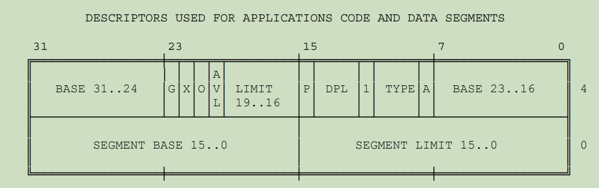
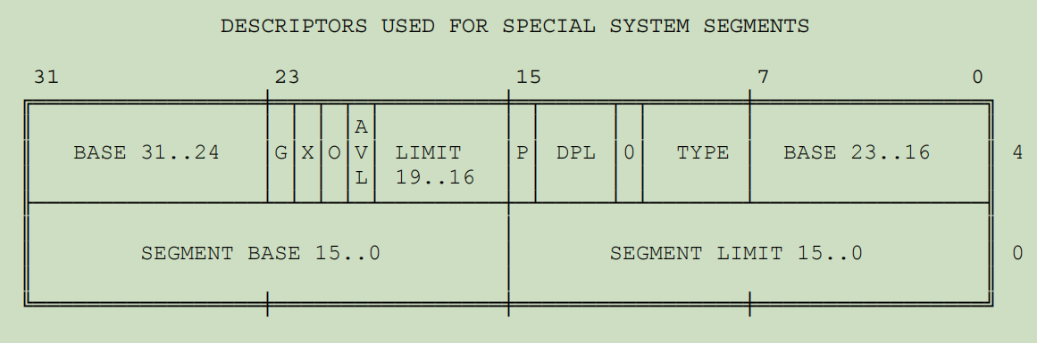
段描述符(segment descriptor)一般不由程序员提供(但是这个实验还是得由你提供)。它的字段如下:
- Base:定义段的位置。有3个部分,cpu将其组合在一起是32位值
- Limit:定义段的大小。有两个部分,cpu组合起来是20位值。这里cpu解释它有两个粒度:1B和4KB。
- Granularity bit(粒度位):置位表示4KB,未置位则表示1B。
- Type(类型):
- Descriptor privilege level(DPL,特权级别):保护机制
- Segment-Present Bit(存在位):为0表示描述符无效(即此时它已经被换出内存了)。和page的类似,如果访问的时候不在的话触发异常。OS如果不同,可以标记该位为
AVALIABLE。 - Accessed bit(访问位):当该段被访问后,置位。用途好像主要是用于基于段实现的虚拟内存OS监控段使用频率(定期测试和清空)
1 | // Application segment type bits |
在<inc/mmu.h>中有一段就是段描述符的宏,SEG_NULL是给第一个元素用的,因为不被使用。
第二个SEG是应用段,采用的格式是上面第一张图片,其中由于一开始A必然为0,而type最低位也是0,所以不需要考虑A的情况,dpl也不需要考虑。
0xC0是一个比较迷惑的点,最高位表示粒度为4KB,还有一位是X,这个在386的手册中并未解释,我翻了IA-32第三卷发现了下面的段描述符格式:
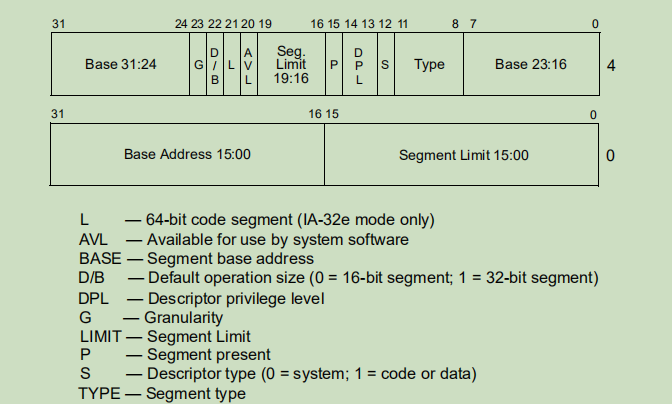
由此看来该位是决定该段是16bit还是32bit,在该实验肯定是32bit,所以置为1。
通过xv6的<asm.h>的注释也可以知道这个描述是没有问题的:
1 | // The 0xC0 means the limit is in 4096-byte units |
(至于386手册为什么没写,可能当时该位不起任何作用?)
段描述符表
有两种描述符表:
- Global Descriptor Table(GDT)
- Local Descriptor Table(LDT)
这个在接下来和lab3都有用,所以有必要讲下。
描述符表示为数组,其中的元素就是8B的描述符(最多8192个元素)。第一个元素并不被cpu使用。
cpu通过GDTR和LDTR寄存器定位GDT和LDT。这两个寄存器存储两个数据:
- base address: 在地址空间的位置
- segment limits:大小
LGDT,SGDT是对GDT的load/store指令,Intel 64 and IA-32 Intel Architecture Software Developer’s Manuals第二卷A有LGDT的说明
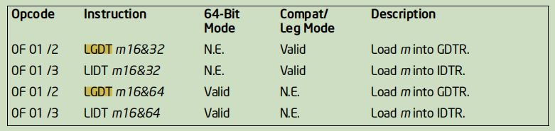
(64的是给64位模式使用的,我们用不到,略)
16bit是limit, 而32bit的是base address。
LGDT的操作数是一个地址,这个地址包含这两个字段:低2字节是大小,高4字节是base address。
在实模式(即本实验中)的用法算是一种惯用法(idiom)
需要注意一点,就是limit实际是$8N-1$,
boot.S
1 | #include <inc/mmu.h> |
代码注释其实写的很详细了,这里讲一下大概的流程:
首先关掉中断,因为原本是用于BIOS初始化工作用的,现在没有必要开启,在内核准备完毕后再打开。
由于各个段寄存器在BIOS工作做完之后,不一定为空,所以需要全部置零。
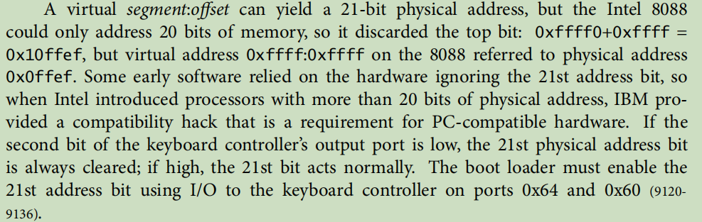
然后是A20使能,这个步骤是为了向后兼容,不搞懂它也没有关系,毕竟是历史遗留。主要是为了强制忽略超过1MB的地址第21位,这样就不会出现与早期PC的兼容性问题。有兴趣可以看下:
之后的一步,就是需要加载GDT,通过它,即使切换到了保护模式,也能保持虚拟地址(或逻辑地址)与物理地址等同,这样内存映射的逻辑不会被打乱。
然后通过CR0(控制寄存器),将PE(Protection Enable)置位,便切换到了保护模式,但还未进入32位模式。
通过ljmp跳转用到的代码段寄存器,切换到了32位模式(因为0xC0),
然后将保护模式下的段寄存器们全部设置为现在的数据段,保持一致。
这里有个小问题就是栈应该设置在哪里?内核会加载到0x100000,而boot loader是0x7c00-0x7e00,由于栈是向下增长,因此可以设为0x7c00,即start标签处(31KB对于boot loader应该够用了)
然后调用bootmain读取内核。
至此,boot.S的工作完成。
main.c
1 |
|
注意文件开头的注释,硬盘的布局如下: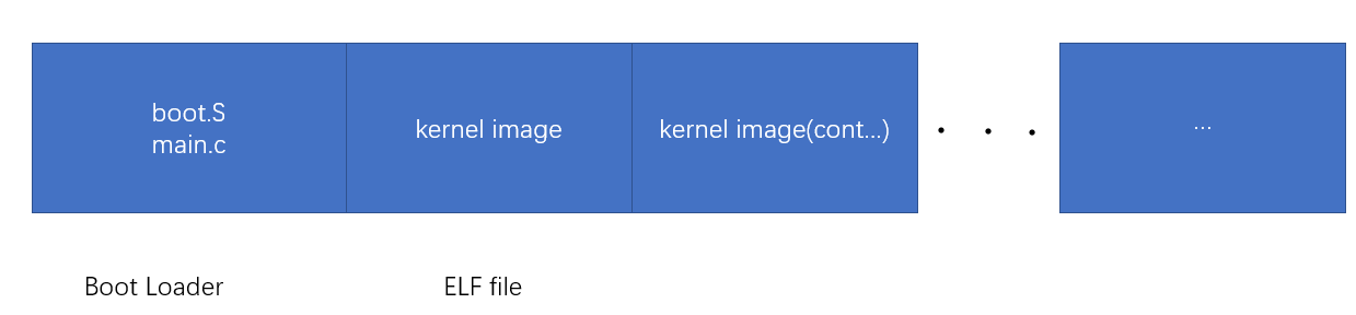
因此能够它会假设内核映像在硬盘上的位置在第二个扇区及之后。
至此,加载内核映像完成。
Boot的流程:
- 加载ROM中的BIOS到内存中并执行它
- BIOS初始化硬件设备,读取第一个扇区(启动扇区)到指定的位置并转交控制给boot loader
- boot loader启动保护模式和设置栈(mov $start, %esp)以至于C代码能够运行,然后调用
bootmain() bootmain()读取内核并转交控制给内核
Debug相关
obj/boot/boot.asm:boot loaderobj/kern/kernel.asm: JOS内核
两个是已经反汇编好的汇编文件,其中装载地址都已经填好了,对于debug来说是很有用的
Question
lab1的文档提了一下问题:
At what point does the processor start executing 32-bit code? What exactly causes the switch from 16- to 32-bit mode?
.code32后都是32位模式ljmp $PROT_MODE_CSEG, $prot_csegWhat is the last instruction of the boot loader executed, and what is the first instruction of the kernel it just loaded?
- 最后的语句应该是
boot/main.c中bootmain函数最后一句,就是调用内核入口函数,不过这里指的是最后的指令,从obj/boot/boot.asm可以看出应为:call *0x10018,这个地址有点特别,这个和ELF有关。 - 内核执行的第一条指令为
movw $0x1234, 0x472(obj/kern/kernel.asm)
Where is the first instruction of the kernel?
应该为kern/entry.S
How does the boot loader decide how many sectors it must read in order to fetch the entire kernel from disk? Where does it find this information?
8个扇区,从boot/main.c中bootmain函数第二条语句可知
Part3: Load Kernel
obj/kern/kernel就是我们的内核映像了,也就是我们常说的可执行文件,文件格式是ELF(Executable and linkable format, 和linux用的一样)。
对这个不熟悉的可以看csapp或《程序员的自我修养》,当然,在课程的reference page也提供了资料:elf.pdf (mit.edu)
然后为了解读ELF文件,要用到objdump工具,看名字就知道是用来解读目标文件(object file)的,使用方式可以通过objdump --help查看。
我们要查看ELF的section,用如下指令:
1 | $ objdump -h obj/kern/kernel |
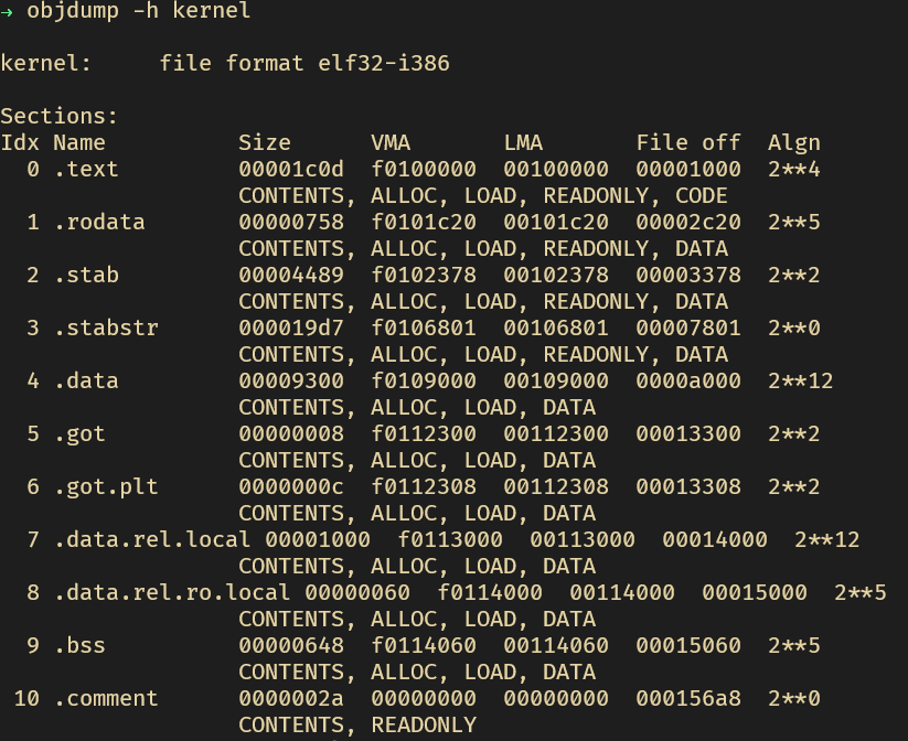
其中,需要注意的是.text的VMA(link address)和LMA(load address)是不一致的,
链接地址是节(section,有的译作“段”,避免混淆,采用“节”)期望执行的内存地址,而装载(或载入)地址是节应该被加载到的内存地址,也就是说最终内核的代码是装载到低地址,而期望执行的是高地址,这算是一种惯用法吧,我只知道linux好像也是这样弄的。